
Setting up your Progressive Dynamics AC/DC panel

The Progressive Dynamics AC/DC panel acts like the breaker panel in a house - it distributes the 120VAC output of your inverter into individual branch circuits, and lets you add a main breaker so that if the cumulative load of all the branch circuits exceeds the capacity of the inverter, the circuit will break. It also gives you 12 fused DC circuits for connecting your 12VDC loads, like lights, pumps, and fans.
Place the Panel
Decide where you will install your AC/DC panel. Ideally this will be within 5 feet of your inverter and distribution blocks.
The panel is designed to be flush-mounted into a cutout in a cabinet or panel. Once you have decided where you will install the AC/DC panel, draw a rectangle you will cut away to install the panel.
The dimensions of the cut-out should be 12.25" x 6". The panel can be mounted in any orientation.

Connect the Inverter
Ensure that your inverter is off, and that your battery breakers are in the disconnected position.
Cut a length of 10-2 Romex long enough to reach the AC/DC panel, and feed it up through the black cable entry gland into the inverter.
Strip back the wire housing and insert the wires into the set of terminals marked "AC1" inside the MultiPlus, which will be the middle set of terminals. Connect the Black wire to the "L" terminal, the White wire to the "N" terminal, and the Green wire to the "GND" terminal, and tighten them down with a small screwdriver.
Connect the AC/DC Panel
Open the AC side of your panel by first lifting out the DC side cover, then lifting out the larger cover, exposing the internal wiring.
Route the Romex cable from the Inverter into your AC/DC panel through one of the knockout ports in the back of the panel.
Strip back the housing on the cable and strip the three wires inside. Using a Phillips screwdriver, connect the white wire to the Neutral busbar on the left, and the Ground busbar on the bottom.

Connect the main breaker.
Slide a 30A breaker (for a MultiPlus 3000) onto the top prong of the "Line" busbar. Ensure that the breaker is in the "OFF" position.
Connect the black wire to the terminal on the breaker and tighten it down with a Philips screwdriver.
This breaker will feed power from the inverter to the Branch breakers installed on the lower prongs. If the cumulative load of all the branch circuits combined exceeds 30 Amps, the main breaker will automatically disconnect.
Install the Branch Breakers
The main breaker ensures that the circuit will break if the total load of all the branch circuits exceeds 30 Amps. The Branch breakers should be smaller than the main breaker. We recommend using 15A or 20A branch breakers. You can add up to 4 branch circuits.
You can then connect 10-2 Romex to these branch breakers, connecting the Line (black) wires to the screw terminals on the breakers, the Neutral (white) wires to the left Neutral busbar, and the Ground (green) wires to the bottom ground busbar.
You can connect the other ends of these wires to outlets or loads. If you are uncertain about how to properly wire these circuits, consult an electrician.


Connect the DC Side of the Panel.
Take a length of Red #6 cable, and strip back one end. Insert the bare wire into the positive terminal on the back of the AC/DC panel.
Note that the Positive terminal has TWO ports. These are both positive, not positive and negative. The extra port is for connecting additional loads or panels, in most cases you will not need it. Connect your positive line to one of the two ports, it does not matter which.
Tighten it down with a hex wrench, and tug on the wires to ensure they are secure.
Connect Your DC Fuse or Breaker
Run the red #6 wire from the panel to where you will mount your 70A fuse, or 80A resettable breaker. Both should be mounted in an accessible location. Give yourself enough wire to run from the panel to one side of the breaker or fuse and cut the red wire.
Strip back the end, and crimp on the corresponding lugs to either side, #10 for a MIDI fuse, and 1/4" for a resettable breaker.
Run the other wire from the breaker or fuse to your positive distribution block, trim any excess wire, strip the end, and insert the bare copper into the distribution block. Tighten down with a hex wrench.


Connect the Negative Line.
Take a length of #6 black wire, strip back the end, and insert it into any of the ports on the rear negative busbar.
Route the black cable to the the negative distribution block, trim any excess wire, strip the end, and insert the bare copper into the negative distribution block. Tighten with a hex wrench.
Install DC Loads and Fuses
Connect your DC loads to the panel by connecting the negative wires to any open port on the rear negative bus bar.
Crimp spade connectors onto the ends of your positive wires, and insert them over the matching positive terminals on the rear left of the panel.
The panel uses DC automotive blade fuses, which are not included, but widely available at auto part stores and hardware stores. For most loads, such as lights and fans, a 10A fuse should be sufficient.
Select fuses that are 5-10A higher than the circuit should draw during normal operation.


You're Done!
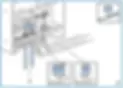
Double check your work against the schematic at the top of this page, and if everything looks good, connect your batteries and turn on your inverter.
The inverter will now feed AC power to each of your circuits.